Regulador PID
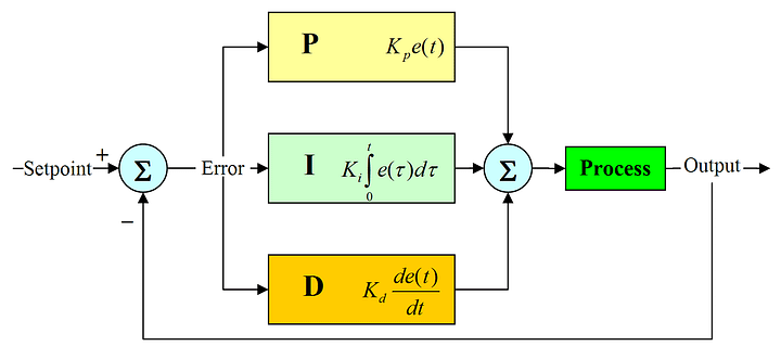
The PID circuit is often utilized as a control loop feedback controller and is very commonly used for many forms of servo circuits. The letters making up the acronym PID correspond to Proportional (P), Integral (I), and Derivative (D), which represents the three control settings of a PID circuit. The purpose of any servo circuit is to hold the system at a predetermined value (set point) for long periods of time. The PID circuit actively controls the system so as to hold it at the set point by generating an error signal that is essentially the difference between the set point and the current value. The three controls relate to the time-dependent error signal; at its simplest, this can be thought of as follows: Proportional is dependent upon the present error, Integral is dependent upon the accumulation of past error, and Derivative is the prediction of future error. The results of each of the controls are then fed into a weighted sum, which then adjusts the output of the circuit, u(t). This output is fed into a control device, its value is fed back into the circuit, and the process is allowed to actively stabilize the circuit’s output to reach and hold at the set point value. The block diagram below illustrates very simply the action of a PID circuit. One or more of the controls can be utilized in any servo circuit depending on system demand and requirement (i.e., P, I, PI, PD, or PID).
Term P is proportional to the current value of the SP − PV error e(t). For example, if the error is large, the control output will be proportionately large by using the gain factor "Kp". Using proportional control alone will result in an error between the set point and the process value because the controller requires an error to generate the proportional output response. In steady state process conditions an equilibrium is reached, with a steady SP-PV "offset".
Term I accounts for past values of the SP − PV error and integrates them over time to produce the I term. For example, if there is a residual SP − PV error after the application of proportional control, the integral term seeks to eliminate the residual error by adding a control effect due to the historic cumulative value of the error. When the error is eliminated, the integral term will cease to grow. This will result in the proportional effect diminishing as the error decreases, but this is compensated for by the growing integral effect.
Term D is a best estimate of the future trend of the SP − PV error, based on its current rate of change. It is sometimes called "anticipatory control", as it is effectively seeking to reduce the effect of the SP − PV error by exerting a control influence generated by the rate of error change. The more rapid the change, the greater the controlling or damping effect.
How to adjust it?
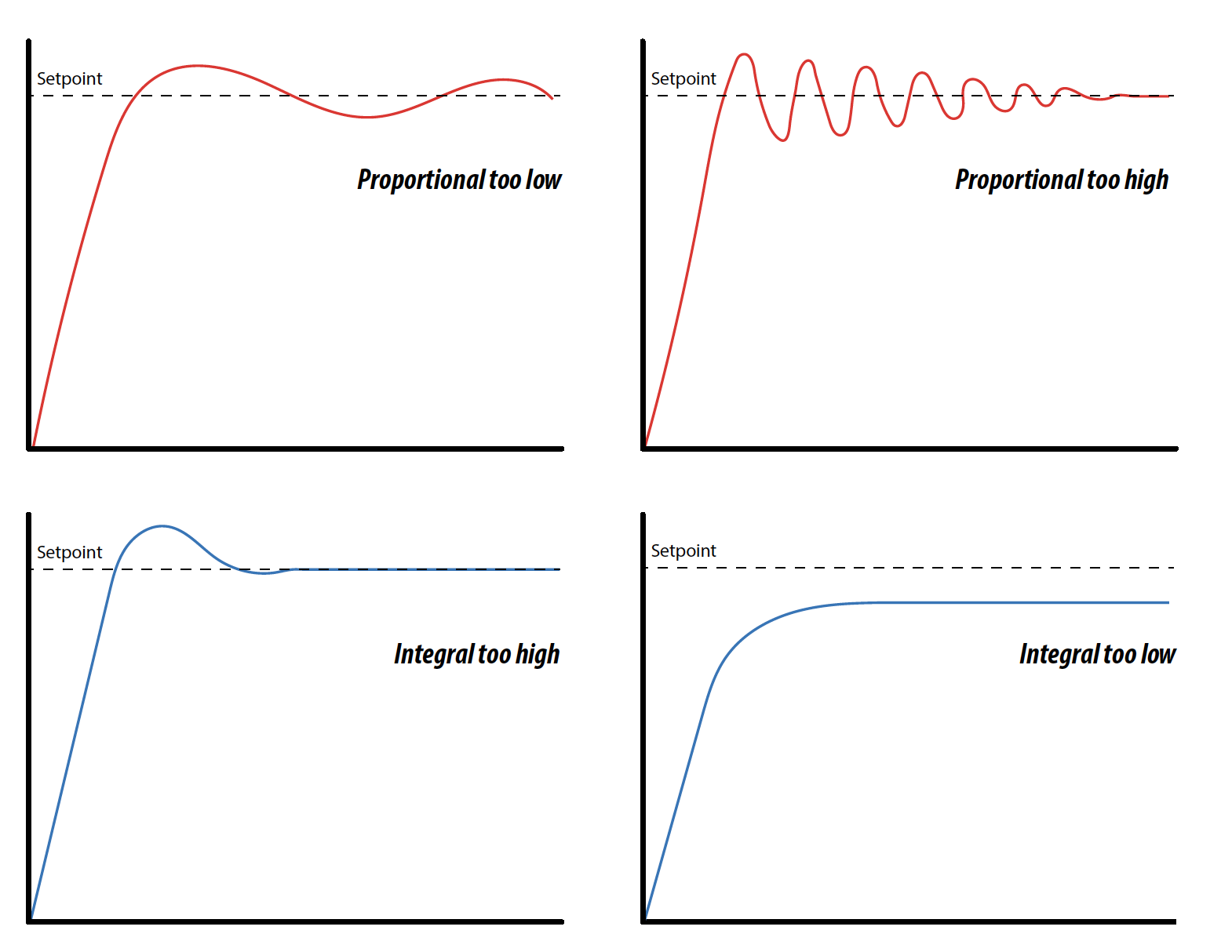
In general the gains of P, I, and D will need to be adjusted by the user in order to best servo the system. While there is not a static set of rules for what the values should be for any specific system, following the general procedures should help in tuning a circuit to match one’s system and environment. In general a PID circuit will typically overshoot the SP value slightly and then quickly damp out to reach the SP value.
Manual tuning of the gain settings is the simplest method for setting the PID controls. However, this procedure is done actively (the PID controller turned on and properly attached to the system) and requires some amount of experience to fully integrate. To tune your PID controller manually, first the integral and derivative gains are set to zero . Increase the proportional gain until you observe oscillation in the output. Your proportional gain should then be set to roughly half this value . After the proportional gain is set, increase the integral gain until any offset is corrected for on a time scale appropriate for your system. If you increase this gain too much, you will observe significant overshoot of the SP value and instability in the circuit. Once the integral gain is set, the derivative gain can then be increased. Derivative gain will reduce overshoot and damp the system quickly to the SP value . If you increase the derivative gain too much, you will see large overshoot (due to the circuit being too slow to respond). By playing with the gain settings, you can maximize the performance of your PID circuit, resulting in a circuit that quickly responds to changes in the system and effectively damps out oscillation about the SP value.
While manual tuning can be very effective at setting a PID circuit for your specific system, it does require some amount of experience and understanding of PID circuits and response. The Ziegler-Nichols method for PID tuning offers a bit more structured guide to setting PID values. Again, you’ll want to set the integral and derivative gain to zero. Increase the proportional gain until the circuit starts to oscillate. We will call this gain level Ku. The oscillation will have a period of Pu. Gains are for various control circuits are then given below in the chart.
Resources:
- https://www.thorlabs.com/newgrouppage9.cfm?objectgroup_id=9013#:~:text=To%20tune%20your%20PID%20controller,to%20roughly%20half%20this%20value.
- https://www.thorlabs.com/newgrouppage9.cfm?objectgroup_id=9013#:~:text=To%20tune%20your%20PID%20controller,to%20roughly%20half%20this%20value.
- https://en.wikipedia.org/wiki/PID_controller
Comentarios
Publicar un comentario